12 September 2010

An analogy for Ohm's Law

Ohm's Law also makes intuitive sense if you apply it to the water-and-pipe analogy. If we have a water pump that exerts pressure (voltage) to push water around a "circuit" (current) through a restriction (resistance), we can model how the three variables interrelate. If the resistance to water flow stays the same and the pump pressure increases, the flow rate must also increase.
If the pressure stays the same and the resistance increases (making it more difficult for the water to flow), then the flow rate must decrease:
If the flow rate were to stay the same while the resistance to flow decreased, the required pressure from the pump would necessarily decrease:
As odd as it may seem, the actual mathematical relationship between pressure, flow, and resistance is actually more complex for fluids like water than it is for electrons. If you pursue further studies in physics, you will discover this for yourself. Thankfully for the electronics student, the mathematics of Ohm's Law is very straightforward and simple.

REVIEW:
  • With resistance steady, current follows voltage (an increase in voltage means an increase in current, and vice versa).
  • With voltage steady, changes in current and resistance are opposite (an increase in current means a decrease in resistance, and vice versa).
  • With current steady, voltage follows resistance (an increase in resistance means an increase in voltage).

How voltage, current, and resistance relate

An electric circuit is formed when a conductive path is created to allow free electrons to continuously move. This continuous movement of free electrons through the conductors of a circuit is called a current, and it is often referred to in terms of "flow," just like the flow of a liquid through a hollow pipe.

The force motivating electrons to "flow" in a circuit is called voltage. Voltage is a specific measure of potential energy that is always relative between two points. When we speak of a certain amount of voltage being present in a circuit, we are referring to the measurement of how much potential energy exists to move electrons from one particular point in that circuit to another particular point. Without reference to two particular points, the term "voltage" has no meaning.

Free electrons tend to move through conductors with some degree of friction, or opposition to motion. This opposition to motion is more properly called resistance. The amount of current in a circuit depends on the amount of voltage available to motivate the electrons, and also the amount of resistance in the circuit to oppose electron flow. Just like voltage, resistance is a quantity relative between two points. For this reason, the quantities of voltage and resistance are often stated as being "between" or "across" two points in a circuit.

To be able to make meaningful statements about these quantities in circuits, we need to be able to describe their quantities in the same way that we might quantify mass, temperature, volume, length, or any other kind of physical quantity. For mass we might use the units of "kilogram" or "gram." For temperature we might use degrees Fahrenheit or degrees Celsius. Here are the standard units of measurement for electrical current, voltage, and resistance:
The "symbol" given for each quantity is the standard alphabetical letter used to represent that quantity in an algebraic equation. Standardized letters like these are common in the disciplines of physics and engineering, and are internationally recognized. The "unit abbreviation" for each quantity represents the alphabetical symbol used as a shorthand notation for its particular unit of measurement. And, yes, that strange-looking "horseshoe" symbol is the capital Greek letter Ω, just a character in a foreign alphabet (apologies to any Greek readers here).

Each unit of measurement is named after a famous experimenter in electricity: The amp after the Frenchman Andre M. Ampere, the volt after the Italian Alessandro Volta, and the ohm after the German Georg Simon Ohm.

The mathematical symbol for each quantity is meaningful as well. The "R" for resistance and the "V" for voltage are both self-explanatory, whereas "I" for current seems a bit weird. The "I" is thought to have been meant to represent "Intensity" (of electron flow), and the other symbol for voltage, "E," stands for "Electromotive force." From what research I've been able to do, there seems to be some dispute over the meaning of "I." The symbols "E" and "V" are interchangeable for the most part, although some texts reserve "E" to represent voltage across a source (such as a battery or generator) and "V" to represent voltage across anything else.

All of these symbols are expressed using capital letters, except in cases where a quantity (especially voltage or current) is described in terms of a brief period of time (called an "instantaneous" value). For example, the voltage of a battery, which is stable over a long period of time, will be symbolized with a capital letter "E," while the voltage peak of a lightning strike at the very instant it hits a power line would most likely be symbolized with a lower-case letter "e" (or lower-case "v") to designate that value as being at a single moment in time. This same lower-case convention holds true for current as well, the lower-case letter "i" representing current at some instant in time. Most direct-current (DC) measurements, however, being stable over time, will be symbolized with capital letters.

One foundational unit of electrical measurement, often taught in the beginnings of electronics courses but used infrequently afterwards, is the unit of the coulomb, which is a measure of electric charge proportional to the number of electrons in an imbalanced state. One coulomb of charge is equal to 6,250,000,000,000,000,000 electrons. The symbol for electric charge quantity is the capital letter "Q," with the unit of coulombs abbreviated by the capital letter "C." It so happens that the unit for electron flow, the amp, is equal to 1 coulomb of electrons passing by a given point in a circuit in 1 second of time. Cast in these terms, current is the rate of electric charge motion through a conductor.

As stated before, voltage is the measure of potential energy per unit charge available to motivate electrons from one point to another. Before we can precisely define what a "volt" is, we must understand how to measure this quantity we call "potential energy." The general metric unit for energy of any kind is the joule, equal to the amount of work performed by a force of 1 newton exerted through a motion of 1 meter (in the same direction). In British units, this is slightly less than 3/4 pound of force exerted over a distance of 1 foot. Put in common terms, it takes about 1 joule of energy to lift a 3/4 pound weight 1 foot off the ground, or to drag something a distance of 1 foot using a parallel pulling force of 3/4 pound. Defined in these scientific terms, 1 volt is equal to 1 joule of electric potential energy per (divided by) 1 coulomb of charge. Thus, a 9 volt battery releases 9 joules of energy for every coulomb of electrons moved through a circuit.

These units and symbols for electrical quantities will become very important to know as we begin to explore the relationships between them in circuits. The first, and perhaps most important, relationship between current, voltage, and resistance is called Ohm's Law, discovered by Georg Simon Ohm and published in his 1827 paper, The Galvanic Circuit Investigated Mathematically. Ohm's principal discovery was that the amount of electric current through a metal conductor in a circuit is directly proportional to the voltage impressed across it, for any given temperature. Ohm expressed his discovery in the form of a simple equation, describing how voltage, current, and resistance interrelate:
In this algebraic expression, voltage (E) is equal to current (I) multiplied by resistance (R). Using algebra techniques, we can manipulate this equation into two variations, solving for I and for R, respectively:
 Let's see how these equations might work to help us analyze simple circuits:
In the above circuit, there is only one source of voltage (the battery, on the left) and only one source of resistance to current (the lamp, on the right). This makes it very easy to apply Ohm's Law. If we know the values of any two of the three quantities (voltage, current, and resistance) in this circuit, we can use Ohm's Law to determine the third.

In this first example, we will calculate the amount of current (I) in a circuit, given values of voltage (E) and resistance (R):
 What is the amount of current (I) in this circuit?
In this second example, we will calculate the amount of resistance (R) in a circuit, given values of voltage (E) and current (I):
What is the amount of resistance (R) offered by the lamp?
In the last example, we will calculate the amount of voltage supplied by a battery, given values of current (I) and resistance (R):
What is the amount of voltage provided by the battery?
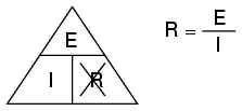
Ohm's Law is a very simple and useful tool for analyzing electric circuits. It is used so often in the study of electricity and electronics that it needs to be committed to memory by the serious student. For those who are not yet comfortable with algebra, there's a trick to remembering how to solve for any one quantity, given the other two. First, arrange the letters E, I, and R in a triangle like this:
If you know E and I, and wish to determine R, just eliminate R from the picture and see what's left:
If you know E and R, and wish to determine I, eliminate I and see what's left:
Lastly, if you know I and R, and wish to determine E, eliminate E and see what's left:
Eventually, you'll have to be familiar with algebra to seriously study electricity and electronics, but this tip can make your first calculations a little easier to remember. If you are comfortable with algebra, all you need to do is commit E=IR to memory and derive the other two formulae from that when you need them!

REVIEW:
  • Voltage measured in volts, symbolized by the letters "E" or "V".
  • Current measured in amps, symbolized by the letter "I".
  • Resistance measured in ohms, symbolized by the letter "R".
  • Ohm's Law: E = IR ; I = E/R ; R = E/I

11 September 2010

Conventional versus electron flow

 "The nice thing about standards is that there are so many of them to choose from." 
- Andrew S. Tanenbaum, computer science professor

When Benjamin Franklin made his conjecture regarding the direction of charge flow (from the smooth wax to the rough wool), he set a precedent for electrical notation that exists to this day, despite the fact that we know electrons are the constituent units of charge, and that they are displaced from the wool to the wax -- not from the wax to the wool -- when those two substances are rubbed together. This is why electrons are said to have a negative charge: because Franklin assumed electric charge moved in the opposite direction that it actually does, and so objects he called "negative" (representing a deficiency of charge) actually have a surplus of electrons.

By the time the true direction of electron flow was discovered, the nomenclature of "positive" and "negative" had already been so well established in the scientific community that no effort was made to change it, although calling electrons "positive" would make more sense in referring to "excess" charge. You see, the terms "positive" and "negative" are human inventions, and as such have no absolute meaning beyond our own conventions of language and scientific description. Franklin could have just as easily referred to a surplus of charge as "black" and a deficiency as "white," in which case scientists would speak of electrons having a "white" charge (assuming the same incorrect conjecture of charge position between wax and wool).

However, because we tend to associate the word "positive" with "surplus" and "negative" with "deficiency," the standard label for electron charge does seem backward. Because of this, many engineers decided to retain the old concept of electricity with "positive" referring to a surplus of charge, and label charge flow (current) accordingly. This became known as conventional flow notation:
Others chose to designate charge flow according to the actual motion of electrons in a circuit. This form of symbology became known as electron flow notation:
In conventional flow notation, we show the motion of charge according to the (technically incorrect) labels of + and -. This way the labels make sense, but the direction of charge flow is incorrect. In electron flow notation, we follow the actual motion of electrons in the circuit, but the + and - labels seem backward. Does it matter, really, how we designate charge flow in a circuit? Not really, so long as we're consistent in the use of our symbols. You may follow an imagined direction of current (conventional flow) or the actual (electron flow) with equal success insofar as circuit analysis is concerned. Concepts of voltage, current, resistance, continuity, and even mathematical treatments such as Ohm's Law (chapter 2) and Kirchhoff's Laws (chapter 6) remain just as valid with either style of notation.

You will find conventional flow notation followed by most electrical engineers, and illustrated in most engineering textbooks. Electron flow is most often seen in introductory textbooks (this one included) and in the writings of professional scientists, especially solid-state physicists who are concerned with the actual motion of electrons in substances. These preferences are cultural, in the sense that certain groups of people have found it advantageous to envision electric current motion in certain ways. Being that most analyses of electric circuits do not depend on a technically accurate depiction of charge flow, the choice between conventional flow notation and electron flow notation is arbitrary . . . almost.

Many electrical devices tolerate real currents of either direction with no difference in operation. Incandescent lamps (the type utilizing a thin metal filament that glows white-hot with sufficient current), for example, produce light with equal efficiency regardless of current direction. They even function well on alternating current (AC), where the direction changes rapidly over time. Conductors and switches operate irrespective of current direction, as well. The technical term for this irrelevance of charge flow is nonpolarization. We could say then, that incandescent lamps, switches, and wires are nonpolarized components. Conversely, any device that functions differently on currents of different direction would be called a polarized device.

There are many such polarized devices used in electric circuits. Most of them are made of so-called semiconductor substances, and as such aren't examined in detail until the third volume of this book series. Like switches, lamps, and batteries, each of these devices is represented in a schematic diagram by a unique symbol. As one might guess, polarized device symbols typically contain an arrow within them, somewhere, to designate a preferred or exclusive direction of current. This is where the competing notations of conventional and electron flow really matter. Because engineers from long ago have settled on conventional flow as their "culture's" standard notation, and because engineers are the same people who invent electrical devices and the symbols representing them, the arrows used in these devices' symbols all point in the direction of conventional flow, not electron flow. That is to say, all of these devices' symbols have arrow marks that point against the actual flow of electrons through them.

Perhaps the best example of a polarized device is the diode. A diode is a one-way "valve" for electric current, analogous to a check valve for those familiar with plumbing and hydraulic systems. Ideally, a diode provides unimpeded flow for current in one direction (little or no resistance), but prevents flow in the other direction (infinite resistance). Its schematic symbol looks like this:
Placed within a battery/lamp circuit, its operation is as such:
When the diode is facing in the proper direction to permit current, the lamp glows. Otherwise, the diode blocks all electron flow just like a break in the circuit, and the lamp will not glow.

If we label the circuit current using conventional flow notation, the arrow symbol of the diode makes perfect sense: the triangular arrowhead points in the direction of charge flow, from positive to negative:
On the other hand, if we use electron flow notation to show the true direction of electron travel around the circuit, the diode's arrow symbology seems backward:
For this reason alone, many people choose to make conventional flow their notation of choice when drawing the direction of charge motion in a circuit. If for no other reason, the symbols associated with semiconductor components like diodes make more sense this way. However, others choose to show the true direction of electron travel so as to avoid having to tell themselves, "just remember the electrons are actually moving the other way" whenever the true direction of electron motion becomes an issue.

In this series of textbooks, I have committed to using electron flow notation. Ironically, this was not my first choice. I found it much easier when I was first learning electronics to use conventional flow notation, primarily because of the directions of semiconductor device symbol arrows. Later, when I began my first formal training in electronics, my instructor insisted on using electron flow notation in his lectures. In fact, he asked that we take our textbooks (which were illustrated using conventional flow notation) and use our pens to change the directions of all the current arrows so as to point the "correct" way! His preference was not arbitrary, though. In his 20-year career as a U.S. Navy electronics technician, he worked on a lot of vacuum-tube equipment. Before the advent of semiconductor components like transistors, devices known as vacuum tubes or electron tubes were used to amplify small electrical signals. These devices work on the phenomenon of electrons hurtling through a vacuum, their rate of flow controlled by voltages applied between metal plates and grids placed within their path, and are best understood when visualized using electron flow notation.

When I graduated from that training program, I went back to my old habit of conventional flow notation, primarily for the sake of minimizing confusion with component symbols, since vacuum tubes are all but obsolete except in special applications. Collecting notes for the writing of this book, I had full intention of illustrating it using conventional flow.

Years later, when I became a teacher of electronics, the curriculum for the program I was going to teach had already been established around the notation of electron flow. Oddly enough, this was due in part to the legacy of my first electronics instructor (the 20-year Navy veteran), but that's another story entirely! Not wanting to confuse students by teaching "differently" from the other instructors, I had to overcome my habit and get used to visualizing electron flow instead of conventional. Because I wanted my book to be a useful resource for my students, I begrudgingly changed plans and illustrated it with all the arrows pointing the "correct" way. Oh well, sometimes you just can't win!

On a positive note (no pun intended), I have subsequently discovered that some students prefer electron flow notation when first learning about the behavior of semiconductive substances. Also, the habit of visualizing electrons flowing against the arrows of polarized device symbols isn't that difficult to learn, and in the end I've found that I can follow the operation of a circuit equally well using either mode of notation. Still, I sometimes wonder if it would all be much easier if we went back to the source of the confusion -- Ben Franklin's errant conjecture -- and fixed the problem there, calling electrons "positive" and protons "negative."

Voltage and current in a practical circuit

Because it takes energy to force electrons to flow against the opposition of a resistance, there will be voltage manifested (or "dropped") between any points in a circuit with resistance between them. It is important to note that although the amount of current (the quantity of electrons moving past a given point every second) is uniform in a simple circuit, the amount of voltage (potential energy per unit charge) between different sets of points in a single circuit may vary considerably:
Take this circuit as an example. If we label four points in this circuit with the numbers 1, 2, 3, and 4, we will find that the amount of current conducted through the wire between points 1 and 2 is exactly the same as the amount of current conducted through the lamp (between points 2 and 3). This same quantity of current passes through the wire between points 3 and 4, and through the battery (between points 1 and 4).

However, we will find the voltage appearing between any two of these points to be directly proportional to the resistance within the conductive path between those two points, given that the amount of current along any part of the circuit's path is the same (which, for this simple circuit, it is). In a normal lamp circuit, the resistance of a lamp will be much greater than the resistance of the connecting wires, so we should expect to see a substantial amount of voltage between points 2 and 3, with very little between points 1 and 2, or between 3 and 4. The voltage between points 1 and 4, of course, will be the full amount of "force" offered by the battery, which will be only slightly greater than the voltage across the lamp (between points 2 and 3).

This, again, is analogous to the water reservoir system:
Between points 2 and 3, where the falling water is releasing energy at the water-wheel, there is a difference of pressure between the two points, reflecting the opposition to the flow of water through the water-wheel. From point 1 to point 2, or from point 3 to point 4, where water is flowing freely through reservoirs with little opposition, there is little or no difference of pressure (no potential energy). However, the rate of water flow in this continuous system is the same everywhere (assuming the water levels in both pond and reservoir are unchanging): through the pump, through the water-wheel, and through all the pipes. So it is with simple electric circuits: the rate of electron flow is the same at every point in the circuit, although voltages may differ between different sets of points.

Resistance

The circuit in the previous section is not a very practical one. In fact, it can be quite dangerous to build (directly connecting the poles of a voltage source together with a single piece of wire). The reason it is dangerous is because the magnitude of electric current may be very large in such a short circuit, and the release of energy very dramatic (usually in the form of heat). Usually, electric circuits are constructed in such a way as to make practical use of that released energy, in as safe a manner as possible.

One practical and popular use of electric current is for the operation of electric lighting. The simplest form of electric lamp is a tiny metal "filament" inside of a clear glass bulb, which glows white-hot ("incandesces") with heat energy when sufficient electric current passes through it. Like the battery, it has two conductive connection points, one for electrons to enter and the other for electrons to exit.

Connected to a source of voltage, an electric lamp circuit looks something like this:
As the electrons work their way through the thin metal filament of the lamp, they encounter more opposition to motion than they typically would in a thick piece of wire. This opposition to electric current depends on the type of material, its cross-sectional area, and its temperature. It is technically known as resistance. (It can be said that conductors have low resistance and insulators have very high resistance.) This resistance serves to limit the amount of current through the circuit with a given amount of voltage supplied by the battery, as compared with the "short circuit" where we had nothing but a wire joining one end of the voltage source (battery) to the other.

When electrons move against the opposition of resistance, "friction" is generated. Just like mechanical friction, the friction produced by electrons flowing against a resistance manifests itself in the form of heat. The concentrated resistance of a lamp's filament results in a relatively large amount of heat energy dissipated at that filament. This heat energy is enough to cause the filament to glow white-hot, producing light, whereas the wires connecting the lamp to the battery (which have much lower resistance) hardly even get warm while conducting the same amount of current.

As in the case of the short circuit, if the continuity of the circuit is broken at any point, electron flow stops throughout the entire circuit. With a lamp in place, this means that it will stop glowing:
As before, with no flow of electrons, the entire potential (voltage) of the battery is available across the break, waiting for the opportunity of a connection to bridge across that break and permit electron flow again. This condition is known as an open circuit, where a break in the continuity of the circuit prevents current throughout. All it takes is a single break in continuity to "open" a circuit. Once any breaks have been connected once again and the continuity of the circuit re-established, it is known as a closed circuit.

What we see here is the basis for switching lamps on and off by remote switches. Because any break in a circuit's continuity results in current stopping throughout the entire circuit, we can use a device designed to intentionally break that continuity (called a switch), mounted at any convenient location that we can run wires to, to control the flow of electrons in the circuit:
This is how a switch mounted on the wall of a house can control a lamp that is mounted down a long hallway, or even in another room, far away from the switch. The switch itself is constructed of a pair of conductive contacts (usually made of some kind of metal) forced together by a mechanical lever actuator or pushbutton. When the contacts touch each other, electrons are able to flow from one to the other and the circuit's continuity is established; when the contacts are separated, electron flow from one to the other is prevented by the insulation of the air between, and the circuit's continuity is broken.

Perhaps the best kind of switch to show for illustration of the basic principle is the "knife" switch:
A knife switch is nothing more than a conductive lever, free to pivot on a hinge, coming into physical contact with one or more stationary contact points which are also conductive. The switch shown in the above illustration is constructed on a porcelain base (an excellent insulating material), using copper (an excellent conductor) for the "blade" and contact points. The handle is plastic to insulate the operator's hand from the conductive blade of the switch when opening or closing it.

Here is another type of knife switch, with two stationary contacts instead of one:
The particular knife switch shown here has one "blade" but two stationary contacts, meaning that it can make or break more than one circuit. For now this is not terribly important to be aware of, just the basic concept of what a switch is and how it works.

Knife switches are great for illustrating the basic principle of how a switch works, but they present distinct safety problems when used in high-power electric circuits. The exposed conductors in a knife switch make accidental contact with the circuit a distinct possibility, and any sparking that may occur between the moving blade and the stationary contact is free to ignite any nearby flammable materials. Most modern switch designs have their moving conductors and contact points sealed inside an insulating case in order to mitigate these hazards. A photograph of a few modern switch types show how the switching mechanisms are much more concealed than with the knife design:
In keeping with the "open" and "closed" terminology of circuits, a switch that is making contact from one connection terminal to the other (example: a knife switch with the blade fully touching the stationary contact point) provides continuity for electrons to flow through, and is called a closed switch. Conversely, a switch that is breaking continuity (example: a knife switch with the blade not touching the stationary contact point) won't allow electrons to pass through and is called an open switch. This terminology is often confusing to the new student of electronics, because the words "open" and "closed" are commonly understood in the context of a door, where "open" is equated with free passage and "closed" with blockage. With electrical switches, these terms have opposite meaning: "open" means no flow while "closed" means free passage of electrons.

REVIEW:
  • Resistance is the measure of opposition to electric current.
  • A short circuit is an electric circuit offering little or no resistance to the flow of electrons. Short circuits are dangerous with high voltage power sources because the high currents encountered can cause large amounts of heat energy to be released.
  • An open circuit is one where the continuity has been broken by an interruption in the path for electrons to flow.
  • A closed circuit is one that is complete, with good continuity throughout.
  • A device designed to open or close a circuit under controlled conditions is called a switch.
  • The terms "open" and "closed" refer to switches as well as entire circuits. An open switch is one without continuity: electrons cannot flow through it. A closed switch is one that provides a direct (low resistance) path for electrons to flow through.

Voltage and current

As was previously mentioned, we need more than just a continuous path (circuit) before a continuous flow of electrons will occur: we also need some means to push these electrons around the circuit. Just like marbles in a tube or water in a pipe, it takes some kind of influencing force to initiate flow. With electrons, this force is the same force at work in static electricity: the force produced by an imbalance of electric charge.

If we take the examples of wax and wool which have been rubbed together, we find that the surplus of electrons in the wax (negative charge) and the deficit of electrons in the wool (positive charge) creates an imbalance of charge between them. This imbalance manifests itself as an attractive force between the two objects:
If a conductive wire is placed between the charged wax and wool, electrons will flow through it, as some of the excess electrons in the wax rush through the wire to get back to the wool, filling the deficiency of electrons there:
The imbalance of electrons between the atoms in the wax and the atoms in the wool creates a force between the two materials. With no path for electrons to flow from the wax to the wool, all this force can do is attract the two objects together. Now that a conductor bridges the insulating gap, however, the force will provoke electrons to flow in a uniform direction through the wire, if only momentarily, until the charge in that area neutralizes and the force between the wax and wool diminishes.

The electric charge formed between these two materials by rubbing them together serves to store a certain amount of energy. This energy is not unlike the energy stored in a high reservoir of water that has been pumped from a lower-level pond:
The influence of gravity on the water in the reservoir creates a force that attempts to move the water down to the lower level again. If a suitable pipe is run from the reservoir back to the pond, water will flow under the influence of gravity down from the reservoir, through the pipe:
It takes energy to pump that water from the low-level pond to the high-level reservoir, and the movement of water through the piping back down to its original level constitutes a releasing of energy stored from previous pumping.

If the water is pumped to an even higher level, it will take even more energy to do so, thus more energy will be stored, and more energy released if the water is allowed to flow through a pipe back down again:
Electrons are not much different. If we rub wax and wool together, we "pump" electrons away from their normal "levels," creating a condition where a force exists between the wax and wool, as the electrons seek to re-establish their former positions (and balance within their respective atoms). The force attracting electrons back to their original positions around the positive nuclei of their atoms is analogous to the force gravity exerts on water in the reservoir, trying to draw it down to its former level.

Just as the pumping of water to a higher level results in energy being stored, "pumping" electrons to create an electric charge imbalance results in a certain amount of energy being stored in that imbalance. And, just as providing a way for water to flow back down from the heights of the reservoir results in a release of that stored energy, providing a way for electrons to flow back to their original "levels" results in a release of stored energy.

When the electrons are poised in that static condition (just like water sitting still, high in a reservoir), the energy stored there is called potential energy, because it has the possibility (potential) of release that has not been fully realized yet. When you scuff your rubber-soled shoes against a fabric carpet on a dry day, you create an imbalance of electric charge between yourself and the carpet. The action of scuffing your feet stores energy in the form of an imbalance of electrons forced from their original locations. This charge (static electricity) is stationary, and you won't realize that energy is being stored at all. However, once you place your hand against a metal doorknob (with lots of electron mobility to neutralize your electric charge), that stored energy will be released in the form of a sudden flow of electrons through your hand, and you will perceive it as an electric shock!

This potential energy, stored in the form of an electric charge imbalance and capable of provoking electrons to flow through a conductor, can be expressed as a term called voltage, which technically is a measure of potential energy per unit charge of electrons, or something a physicist would call specific potential energy. Defined in the context of static electricity, voltage is the measure of work required to move a unit charge from one location to another, against the force which tries to keep electric charges balanced. In the context of electrical power sources, voltage is the amount of potential energy available (work to be done) per unit charge, to move electrons through a conductor.

Because voltage is an expression of potential energy, representing the possibility or potential for energy release as the electrons move from one "level" to another, it is always referenced between two points. Consider the water reservoir analogy:
Because of the difference in the height of the drop, there's potential for much more energy to be released from the reservoir through the piping to location 2 than to location 1. The principle can be intuitively understood in dropping a rock: which results in a more violent impact, a rock dropped from a height of one foot, or the same rock dropped from a height of one mile? Obviously, the drop of greater height results in greater energy released (a more violent impact). We cannot assess the amount of stored energy in a water reservoir simply by measuring the volume of water any more than we can predict the severity of a falling rock's impact simply from knowing the weight of the rock: in both cases we must also consider how far these masses will drop from their initial height. The amount of energy released by allowing a mass to drop is relative to the distance between its starting and ending points. Likewise, the potential energy available for moving electrons from one point to another is relative to those two points. Therefore, voltage is always expressed as a quantity between two points. Interestingly enough, the analogy of a mass potentially "dropping" from one height to another is such an apt model that voltage between two points is sometimes called a voltage drop.

Voltage can be generated by means other than rubbing certain types of materials against each other. Chemical reactions, radiant energy, and the influence of magnetism on conductors are a few ways in which voltage may be produced. Respective examples of these three sources of voltage are batteries, solar cells, and generators (such as the "alternator" unit under the hood of your automobile). For now, we won't go into detail as to how each of these voltage sources works -- more important is that we understand how voltage sources can be applied to create electron flow in a circuit.

Let's take the symbol for a chemical battery and build a circuit step by step:
Any source of voltage, including batteries, have two points for electrical contact. In this case, we have point 1 and point 2 in the above diagram. The horizontal lines of varying length indicate that this is a battery, and they further indicate the direction which this battery's voltage will try to push electrons through a circuit. The fact that the horizontal lines in the battery symbol appear separated (and thus unable to serve as a path for electrons to move) is no cause for concern: in real life, those horizontal lines represent metallic plates immersed in a liquid or semi-solid material that not only conducts electrons, but also generates the voltage to push them along by interacting with the plates.

Notice the little "+" and "-" signs to the immediate left of the battery symbol. The negative (-) end of the battery is always the end with the shortest dash, and the positive (+) end of the battery is always the end with the longest dash. Since we have decided to call electrons "negatively" charged (thanks, Ben!), the negative end of a battery is that end which tries to push electrons out of it. Likewise, the positive end is that end which tries to attract electrons.

With the "+" and "-" ends of the battery not connected to anything, there will be voltage between those two points, but there will be no flow of electrons through the battery, because there is no continuous path for the electrons to move.
The same principle holds true for the water reservoir and pump analogy: without a return pipe back to the pond, stored energy in the reservoir cannot be released in the form of water flow. Once the reservoir is completely filled up, no flow can occur, no matter how much pressure the pump may generate. There needs to be a complete path (circuit) for water to flow from the pond, to the reservoir, and back to the pond in order for continuous flow to occur.

We can provide such a path for the battery by connecting a piece of wire from one end of the battery to the other. Forming a circuit with a loop of wire, we will initiate a continuous flow of electrons in a clockwise direction:
So long as the battery continues to produce voltage and the continuity of the electrical path isn't broken, electrons will continue to flow in the circuit. Following the metaphor of water moving through a pipe, this continuous, uniform flow of electrons through the circuit is called a current. So long as the voltage source keeps "pushing" in the same direction, the electron flow will continue to move in the same direction in the circuit. This single-direction flow of electrons is called a Direct Current, or DC. In the second volume of this book series, electric circuits are explored where the direction of current switches back and forth: Alternating Current, or AC. But for now, we'll just concern ourselves with DC circuits.

Because electric current is composed of individual electrons flowing in unison through a conductor by moving along and pushing on the electrons ahead, just like marbles through a tube or water through a pipe, the amount of flow throughout a single circuit will be the same at any point. If we were to monitor a cross-section of the wire in a single circuit, counting the electrons flowing by, we would notice the exact same quantity per unit of time as in any other part of the circuit, regardless of conductor length or conductor diameter.

If we break the circuit's continuity at any point, the electric current will cease in the entire loop, and the full voltage produced by the battery will be manifested across the break, between the wire ends that used to be connected:
Notice the "+" and "-" signs drawn at the ends of the break in the circuit, and how they correspond to the "+" and "-" signs next to the battery's terminals. These markers indicate the direction that the voltage attempts to push electron flow, that potential direction commonly referred to as polarity. Remember that voltage is always relative between two points. Because of this fact, the polarity of a voltage drop is also relative between two points: whether a point in a circuit gets labeled with a "+" or a "-" depends on the other point to which it is referenced. Take a look at the following circuit, where each corner of the loop is marked with a number for reference:
With the circuit's continuity broken between points 2 and 3, the polarity of the voltage dropped between points 2 and 3 is "-" for point 2 and "+" for point 3. The battery's polarity (1 "-" and 4 "+") is trying to push electrons through the loop clockwise from 1 to 2 to 3 to 4 and back to 1 again.

Now let's see what happens if we connect points 2 and 3 back together again, but place a break in the circuit between points 3 and 4:
With the break between 3 and 4, the polarity of the voltage drop between those two points is "+" for 4 and "-" for 3. Take special note of the fact that point 3's "sign" is opposite of that in the first example, where the break was between points 2 and 3 (where point 3 was labeled "+"). It is impossible for us to say that point 3 in this circuit will always be either "+" or "-", because polarity, like voltage itself, is not specific to a single point, but is always relative between two points!

REVIEW:
  • Electrons can be motivated to flow through a conductor by the same force manifested in static electricity.
  • Voltage is the measure of specific potential energy (potential energy per unit charge) between two locations. In layman's terms, it is the measure of "push" available to motivate electrons.
  • Voltage, as an expression of potential energy, is always relative between two locations, or points. Sometimes it is called a voltage "drop."
  • When a voltage source is connected to a circuit, the voltage will cause a uniform flow of electrons through that circuit called a current.
  • In a single (one loop) circuit, the amount of current at any point is the same as the amount of current at any other point.
  • If a circuit containing a voltage source is broken, the full voltage of that source will appear across the points of the break.
  • The +/- orientation of a voltage drop is called the polarity. It is also relative between two points.

Electric circuits

You might have been wondering how electrons can continuously flow in a uniform direction through wires without the benefit of these hypothetical electron Sources and Destinations. In order for the Source-and-Destination scheme to work, both would have to have an infinite capacity for electrons in order to sustain a continuous flow! Using the marble-and-tube analogy, the marble source and marble destination buckets would have to be infinitely large to contain enough marble capacity for a "flow" of marbles to be sustained.

The answer to this paradox is found in the concept of a circuit: a never-ending looped pathway for electrons. If we take a wire, or many wires joined end-to-end, and loop it around so that it forms a continuous pathway, we have the means to support a uniform flow of electrons without having to resort to infinite Sources and Destinations:
Each electron advancing clockwise in this circuit pushes on the one in front of it, which pushes on the one in front of it, and so on, and so on, just like a hula-hoop filled with marbles. Now, we have the capability of supporting a continuous flow of electrons indefinitely without the need for infinite electron supplies and dumps. All we need to maintain this flow is a continuous means of motivation for those electrons, which we'll address in the next section of this chapter.

It must be realized that continuity is just as important in a circuit as it is in a straight piece of wire. Just as in the example with the straight piece of wire between the electron Source and Destination, any break in this circuit will prevent electrons from flowing through it:
An important principle to realize here is that it doesn't matter where the break occurs. Any discontinuity in the circuit will prevent electron flow throughout the entire circuit. Unless there is a continuous, unbroken loop of conductive material for electrons to flow through, a sustained flow simply cannot be maintained.
REVIEW:
  • A circuit is an unbroken loop of conductive material that allows electrons to flow through continuously without beginning or end.
  • If a circuit is "broken," that means its conductive elements no longer form a complete path, and continuous electron flow cannot occur in it.
  • The location of a break in a circuit is irrelevant to its inability to sustain continuous electron flow. Any break, anywhere in a circuit prevents electron flow throughout the circuit.